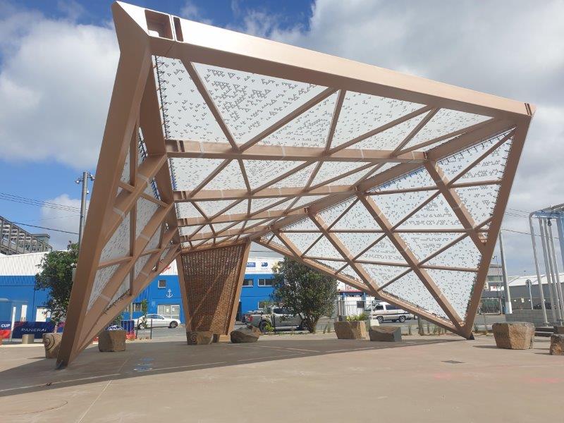
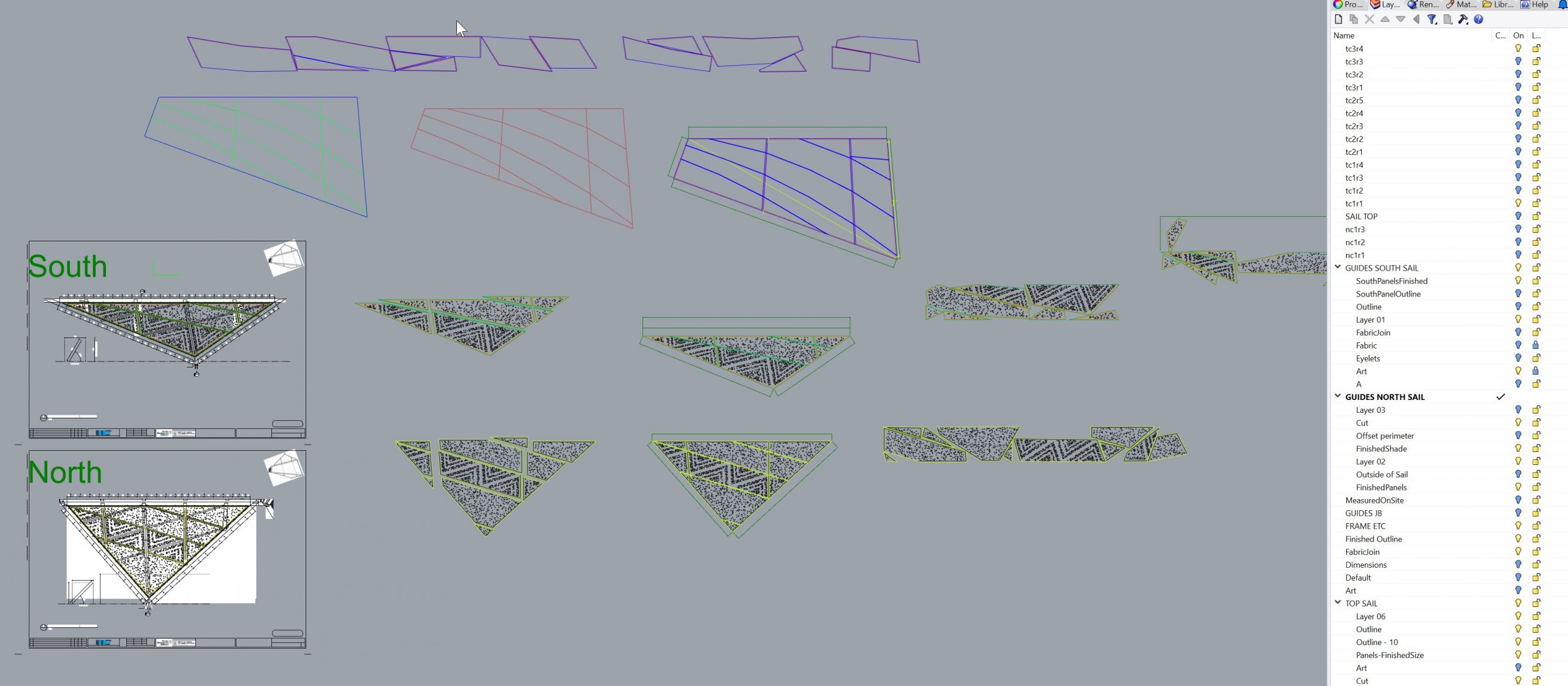
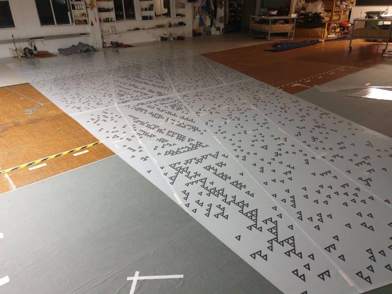
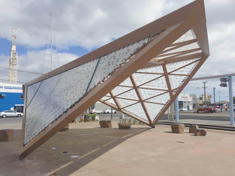
Just prior to manufacture it was decided that it would be preferable that any joins in the fabric not be visible from the ground looking up. This was achieved by designing joins to run along the lattice-work of the steel structure. This complicated panelling somewhat because of the asymmetric nature of the structure. We loaded the plans for the structure into CAD and then worked to create panels that followed the lattice work nature of the structure while staying within the width of the chosen fabric. This resulted in 27 irregular-shaped panels, and a number of joins that were not straight.
The irregular shape of the panels made achieving good fabric yield challenging. Nesting algorithms were run a number of times to achieve the best possible fabric yield – left to run for a few hours, this software ran millions of iterations of panel layout and rotation to achieve the best possible fabric yield.
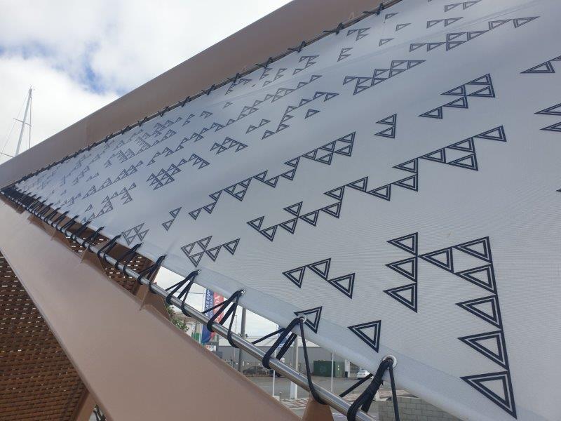
Having optimised the fabric usage, the panels were then recombined and prepared for print and manufacture in CAD. As well as overlaying and printing the artwork, a number of colour-coded elements were added to the print output – this included: finished outlines, cutting lines, eyelet placements, panel numbers and alignment check-marks. Panel numbers and check-marks proved invaluable when bringing together the trimmed out panels, which had all been muddled up as they were rearranged and rotated during the nesting process.

